Shandilya Energy Systems Pvt. Ltd.
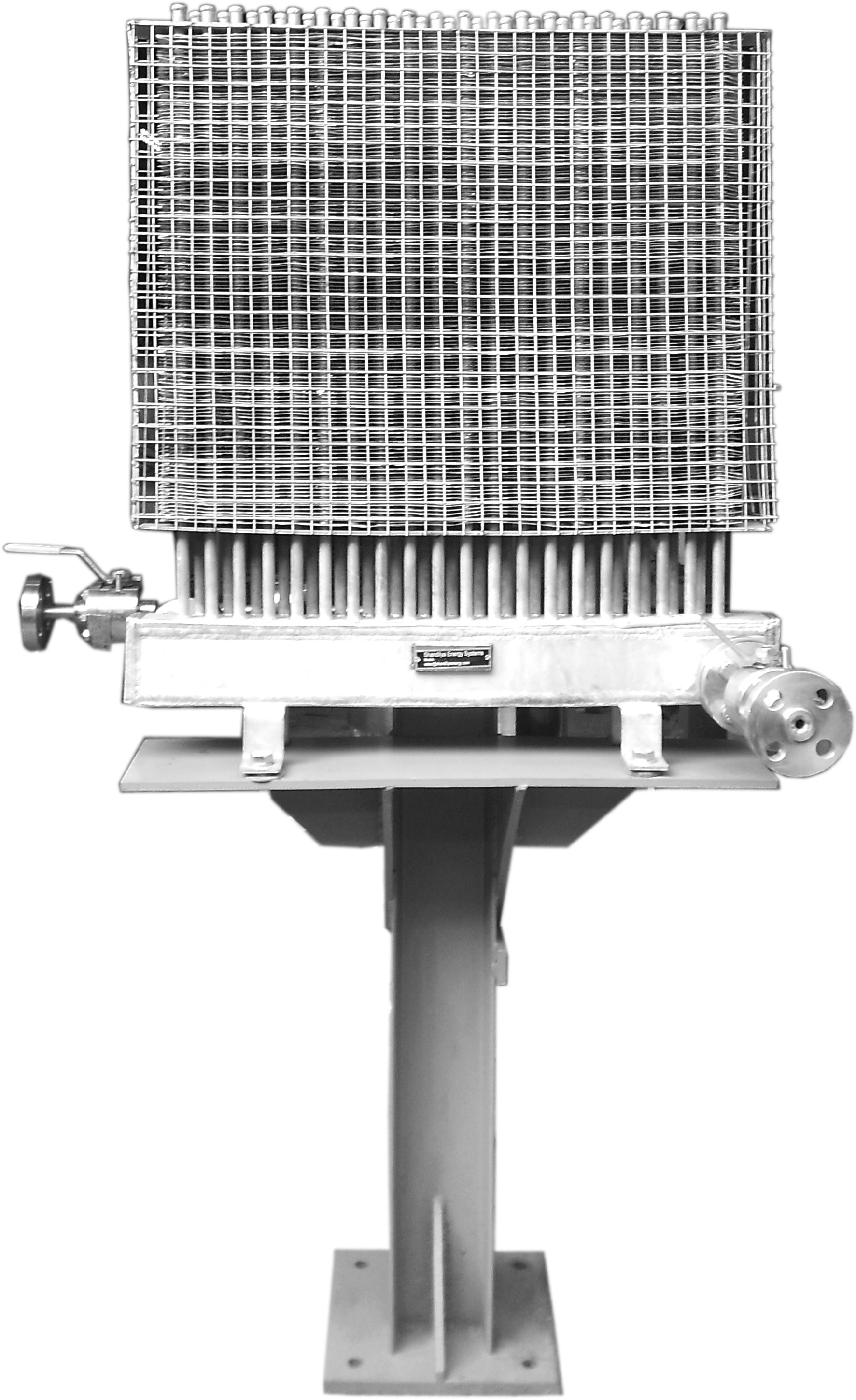
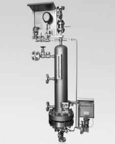
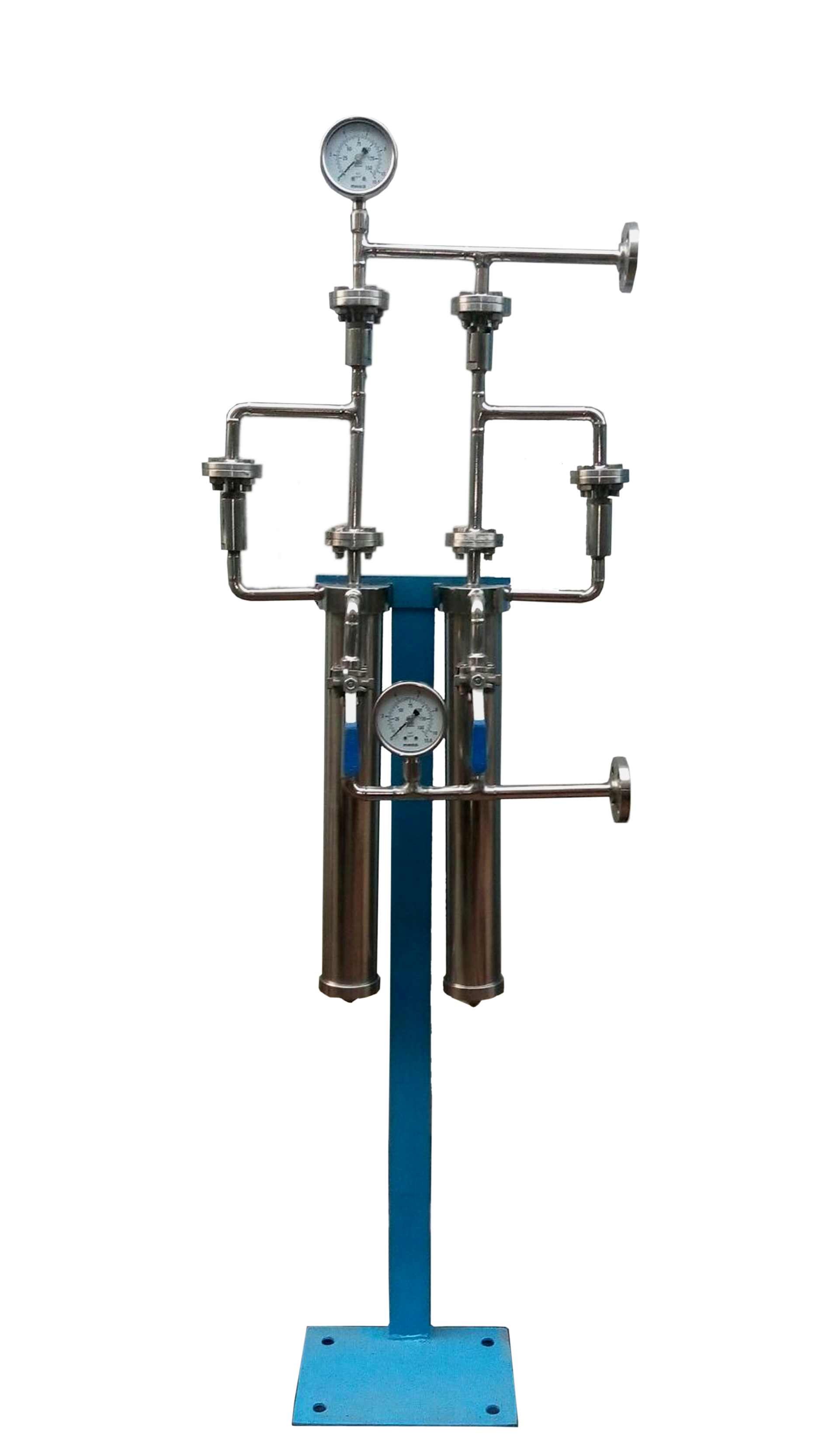
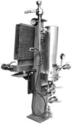
Manufacturer of Natural Draft Air Finned Cooler For Mechanical Seal, API Plan 52, 53A and 53C, Magnetic Level Indicator, Water filter For Mechanical Seals
|
|
Shandilya Energy Systems Pvt. Ltd.
|
|
Manufacturer of Natural Draft Air Finned Cooler For Mechanical Seal, API Plan 52, 53A and 53C, Magnetic Level Indicator, Water filter For Mechanical Seals |
|
|
|
|
|
|
||||||
|
Advantages We do not want that a toxic, volatile or flammable liquid should leak to atmosphere. In such case normally double seals are recommended for pumps. API (American Petroleum Institute) has recommended various plans (API Plan 52, 53A, 53B and 53C) in standard API 682 for double seals (In earlier editions only API Plan 52 and 53 were there. Now API Plan 53 B and 53C have been added and old plan 53 is renamed as API Plan 53A.) All three API Plan 53 versions are intended to isolate the pumped product from the atmosphere and create a favourable environment for the mechanical seal. All the above plans are explained in short below, API Plan 52 52The buffer liquid is provided in a reservoir for the outer seal of a double seal. During normal operation, an internal pumping ring maintains circulation. The reservoir is usually continuously vented to a vapour recovery system and is maintained at a pressure less than the pressure in the seal chamber. The system is not good for volatile fluids. It allows vapour to go to the flare. Actual loss of product is not known. For vapour pressure more than 5kg/cm2 (abs) , API Plan 52 is not recommended (ref OISD-STD-125)
API Plan 53A 53A The barrier fluid is maintained in a reservoir. The barrier fluid is pressurized by an external source (Nitrogen cylinder or a regulated supply of Nitrogen). Normally a pumping ring is provided in between the two seals. It circulates the barrier fluid through the loop. In the reservoir normally a cooling coil is provided which removes the heat from the barrier fluid. The reservoir as well provides makeup fluid for normal seal leakage. Excessive seal leakage is detected by a change in fluid level in the reservoir.
The primary disadvantage of this plan is that there is an interface between the Nitrogen and the barrier fluid. At higher pressures, this can lead to significant gas absorption into the barrier fluid resulting in premature failure of seal because of the gas liberation of the seal face. This Plan is recommended only up to 10 kg/cm2 pressure. Other disadvantage is that the barrier fluid pressure is maintained higher than the maximum stuffing box pressure. The Outboard seal faces maximum pressure all the time. Also inboard seal faces variable differential pressure.
API Plan 53B 53B Plan 53B is a dual pressurized system that eliminates direct Nitrogen contact with the barrier liquid (Improvement in Plan 53A). The Plan 53B uses a bladder accumulator, which acts as a barrier between the Nitrogen gas and the barrier fluid. The bladder is pressurized with Nitrogen prior to filling the system with barrier liquid. As the system is filled, the bladder is compressed by barrier liquid. The over pressurized Nitrogen provides constant pressure on the barrier liquid. A pumping ring circulates the barrier fluid through a loop that includes a seal cooler and other instrumentation. Excessive seal leakage is detected by drop in the pressure in the seal loop.
The disadvantage is that the barrier fluid pressure is maintained higher than the maximum stuffing box press. Outboard seal faces maximum pressure all the time. Also inboard seal faces variable differential pressure. In this plan separate cooler is recommended, the separate heat exchanger introduces additional flow resistance to the piping system and this may affect the circulation of the barrier fluid.
API PLAN 53 C 53C Plan 53C is a dual pressurized system that eliminates the use of Nitrogen for pressurization with the help of a piston accumulator. Barrier liquid is stored on the topside of the piston. The seal chamber is connected to the bottom of the piston accumulator. Piston design is such that slightly higher pressure is generated at the top of the accumulator (with the help of initial pressure provided by spring and differential pressure created by Piston). The top portion of accumulator is connected into the seal loop. A pumping ring circulates the barrier fluid through a loop that includes a seal cooler and other instrumentation. The leakage is detected by change in level. This system is ideal for applications that have fluctuating pressures. Since the piston accumulator pressurizes the barrier fluid based on the stuffing box pressure, the barrier pressure automatically tracks actual operating conditions including system upset.
In Plan 53 C barrier fluid pressure is maintained slightly higher than actual stuffing box pressure all the time. Therefore the outboard seal is subjected to less pressure in comparison with Plan 53A and Plan 53B. The inboard seal faces constant differential pressure which is an improvement upon Plan 53 A and Plan 53 B. In this plan also separate cooler is recommended, the separate heat exchanger introduces additional flow resistance to the piping system and this may affect the circulation of the barrier fluid. In this plan, the barrier Fluid and Process Fluid are separated by the ‘O’ Ring (mounted on the Piston). When the leakage takes place, barrier fluid pressure reduces and piston moves upwards to compensate the pressure loss. The presence of ‘O’ Ring makes movement of piston sluggish resulting in poor response of the piston. The system becomes less reliable. This system is ideal for applications that have fluctuating operating pressures and higher pressure in stuffing box chamber. Used with dual pressurized seals to isolate process fluid (that is usually hazardous /toxic in nature).
Drawback of the piston type of system: 1. The response of the system is poor at low stuffing box pressure. 2. The presence of ‘O’ Ring makes movement of piston sluggish. Therefore pressure tracking is poor. 3. Due to sluggish movement of piston system does not recognize slight leakage.
Shandilya Modified Plan 53 C SE Shandilya has replaced piston with metal bellow. Operation Principle: The Metal Bellow Tracker provides a simple means of pressurizing double pressurised , mechanical seals. It automatically adjusts to maintain seal pressure during normal barrier fluid leakage. Therefore, barrier fluid pressure is constantly referenced to the sealed pressure and maintains differential pressure across inner primary seal face in the range of 15 to 30 PSI (1 to 2 Bar). This is regardless of any suction pressure changes and provides ideal operating conditions for the mechanical seal. The Metal Bellow Tracker achieves this without need of external nitrogen gas supplies, external pumps, power supplies, or bladder accumulators. Since no ‘O’ ring is being used for separating the process side fluid and barrier fluid, it eliminates the sluggish motion / poor response of piston. The bellow provides immediate response of the pressure change on process side pressure to the barrier fluid pressure.
|
||||||
|
|
||||||
|
||||||